I’m a student at Southampton University, studying MEng Electronic and Electrical Engineering.
Below is a sample of some of the circuits I’ve designed recently (2022-24).
PCBs
| Schematic | PCB | Description |
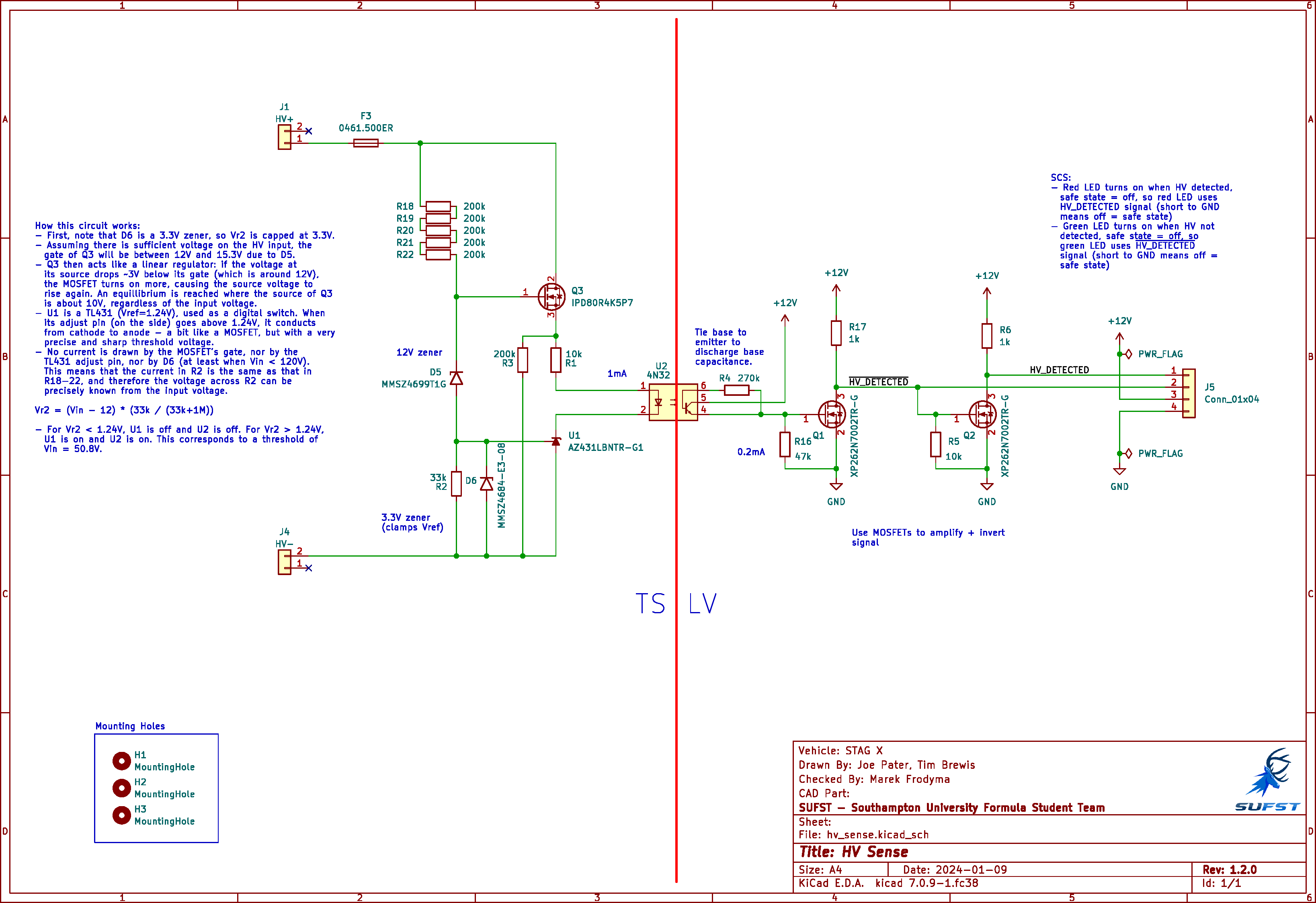 | 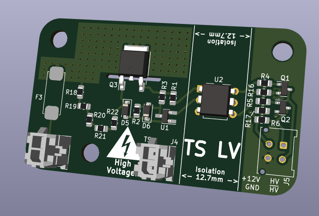 | This is a PCB I design for Formula Student. It takes the battery voltage as input and has an isolated digital output. The output is high whenever the measured voltage exceeds 60V. The circuit uses a TL431 adjustable voltage regulator to compare the (stepped down) input to its internal reference. A MOSFET-based linear regulator steps down the input to drive the optocoupler. A clever trick here was to use the resistor chain R18-22 both to supply the MOSFET’s gate voltage, and as part of a voltage divider for input measurement. |
  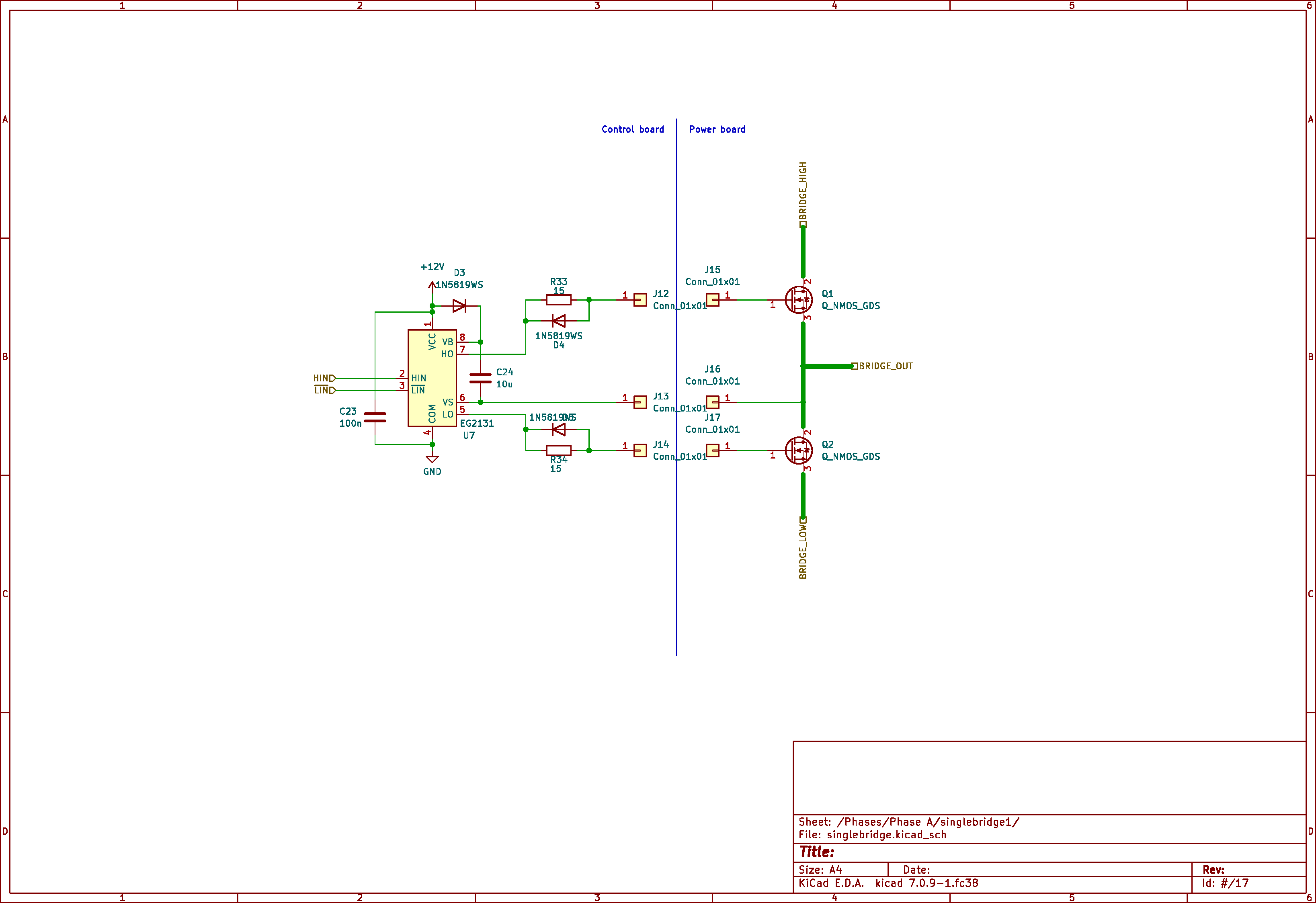 | 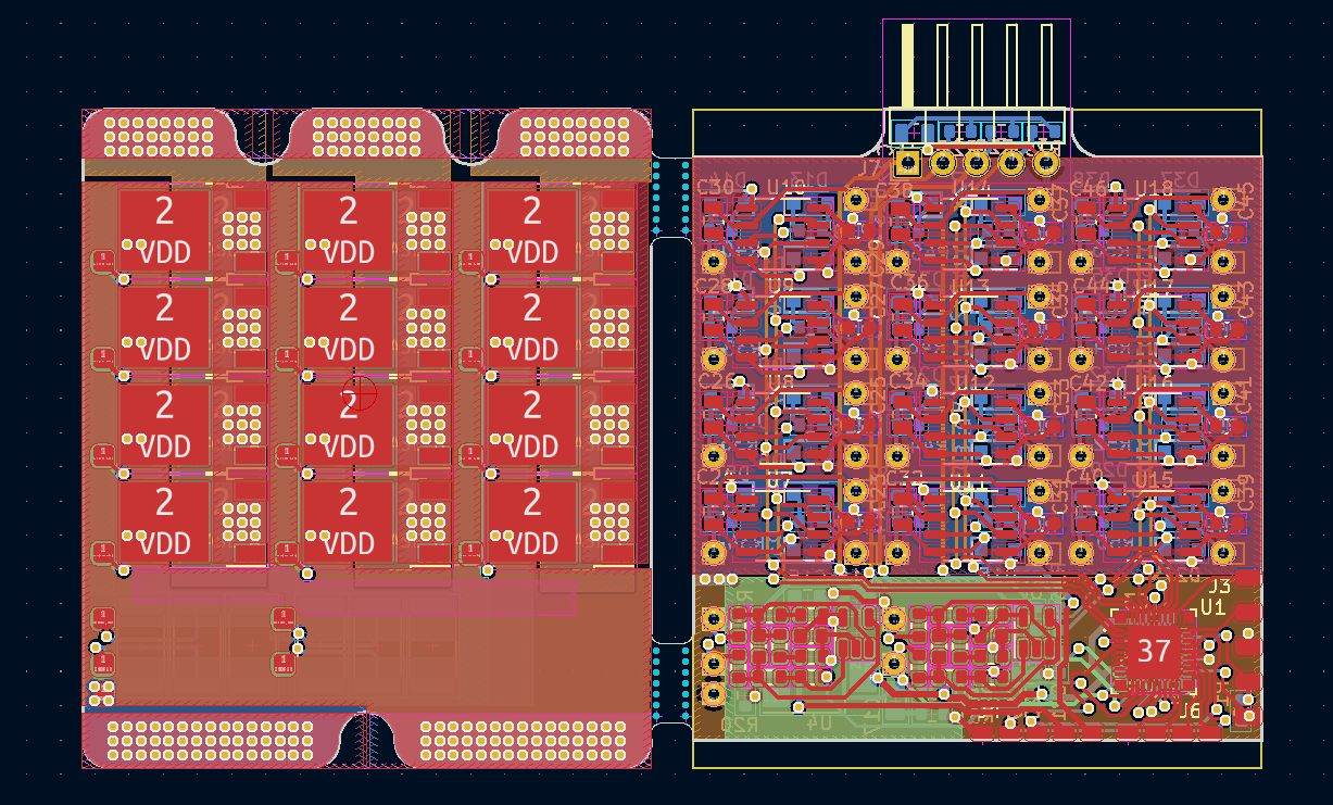 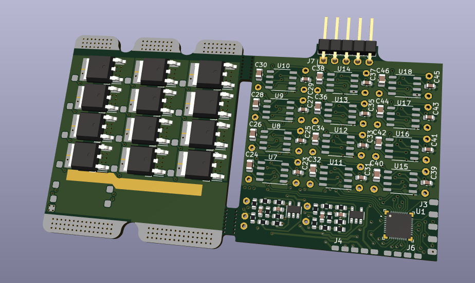 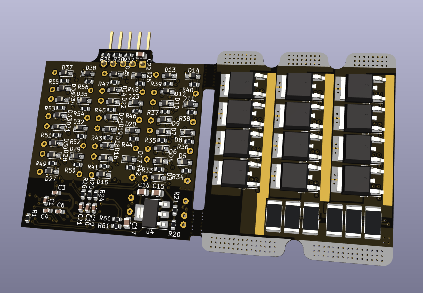 | This is a 3-phase Field Oriented Control motor driver I designed for a Robotics Society project. The challenge here was optimising for cost, size and efficiency – we needed 12 of these in total, so the budget was roughly £15 each! My solution was to buy cheap (10p) MOSFETs from LCSC (rated for 80A, 30V!), and then to put four of these in parallel for a total of 24 MOSFETs per gate driver. I used 12 * 15p bootstrap-style gate drivers (rated for 0.5A) to drive the MOSFETs. The microcontroller was a PIC16F33CK64MC103. To reduce size, the system has two densely-packed 4 layer PCBs stacked on top of each other, with wires dropping down from the “gate driver & MCU” board to the MOSFET board. The code was written in C and (for the complex maths) Assembly. |
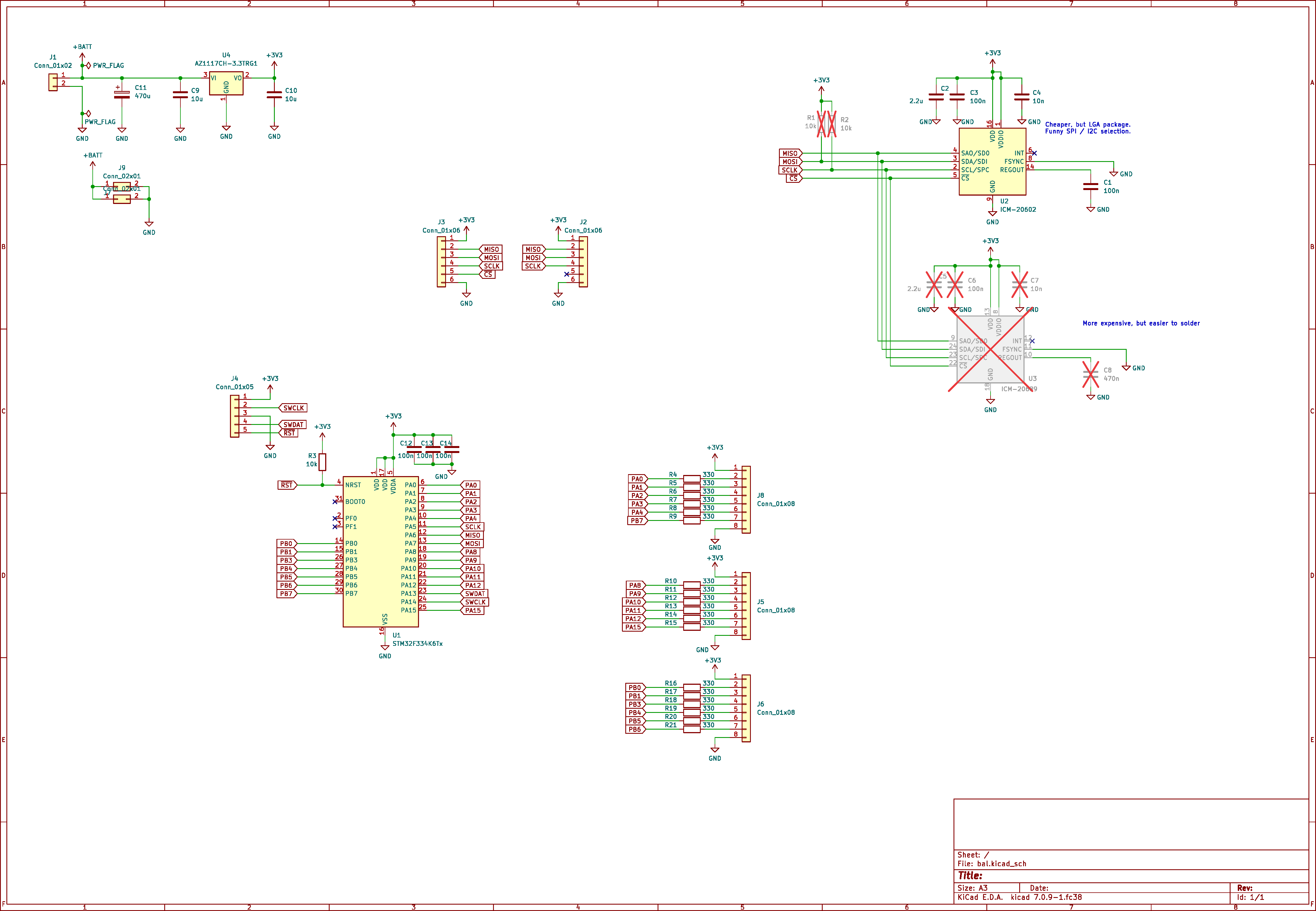 | 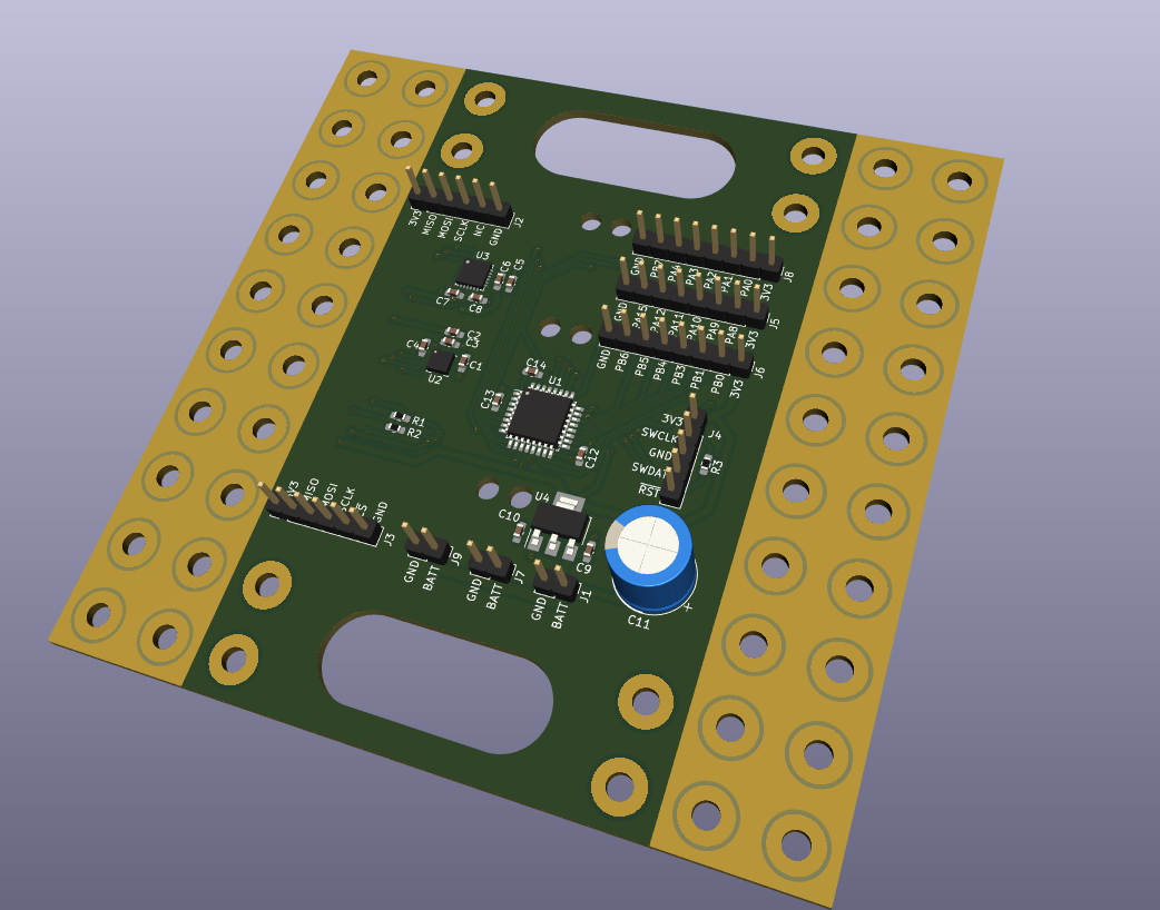 | PCB for balancing robot – Simple PCB with MCU and IMU – PCB designed for mechanical support |
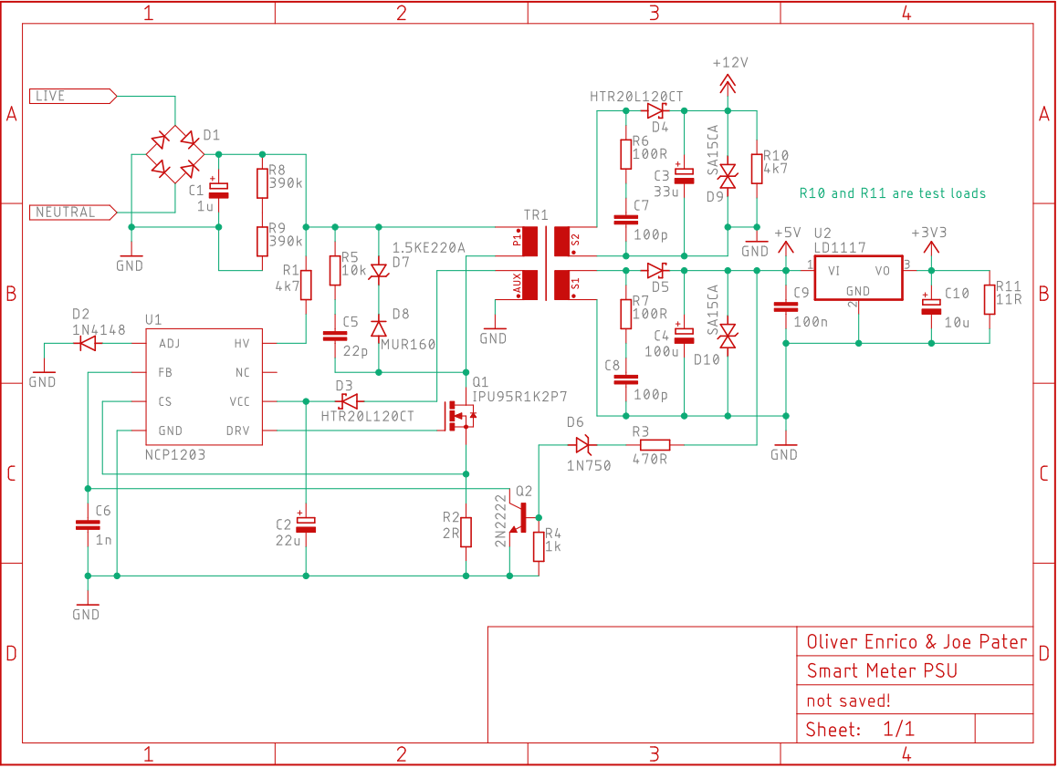 | Mains 1W flyback converter – Transformer designed from scratch | |
  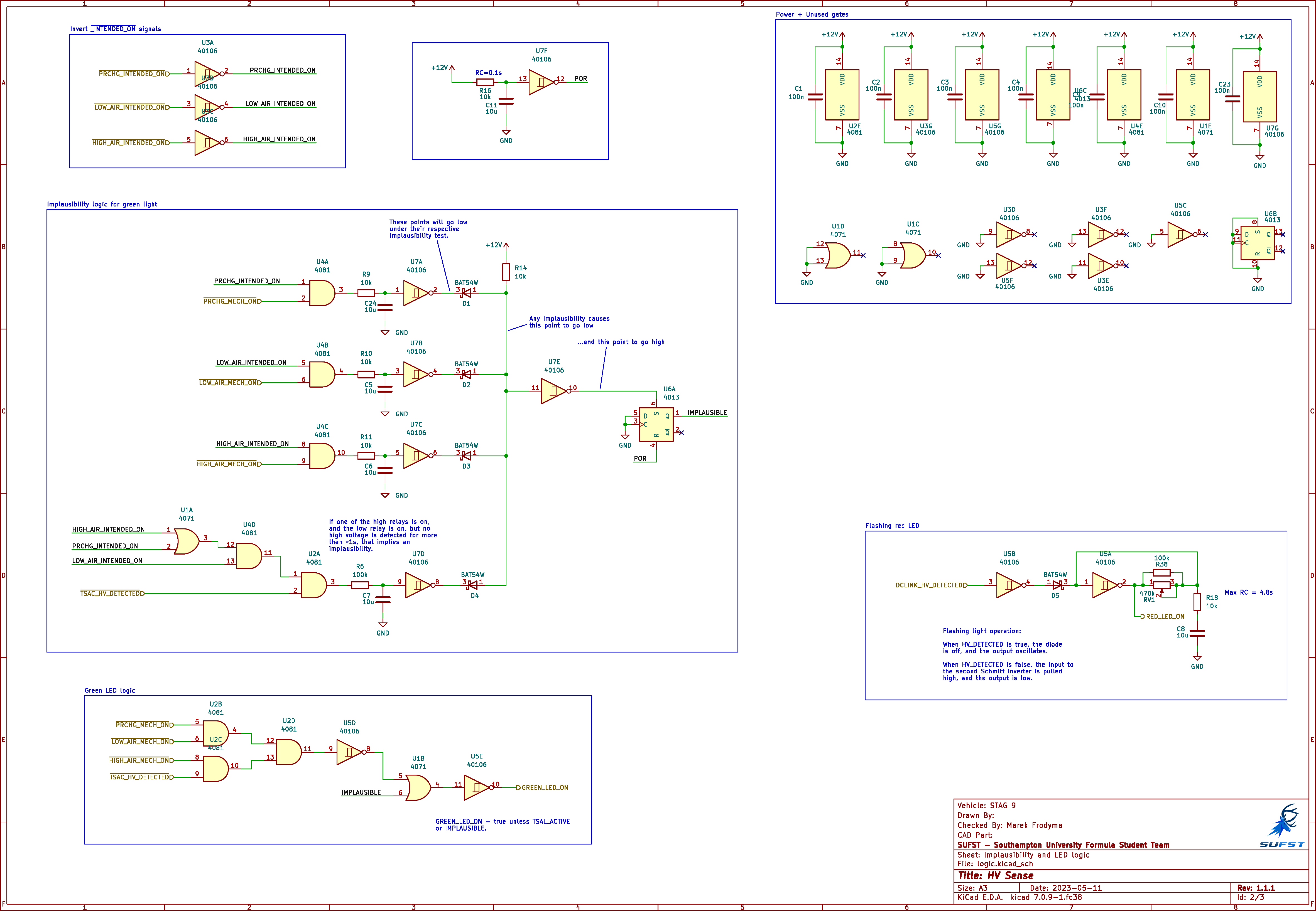 | 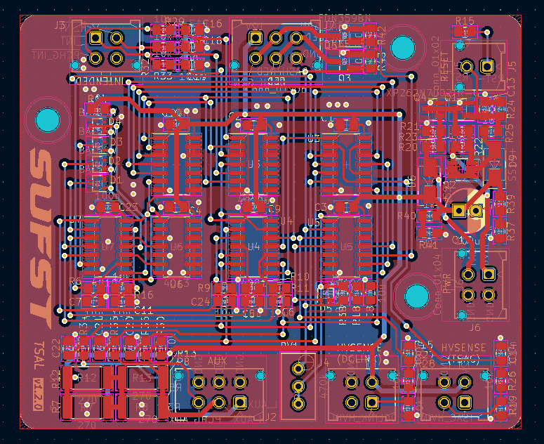 | Formula Student “Tractive System Active Light”. – Latching MOSFET power switch designed to minimise battery power consumption when off (~1nA) – Logic circuits designed around rules |
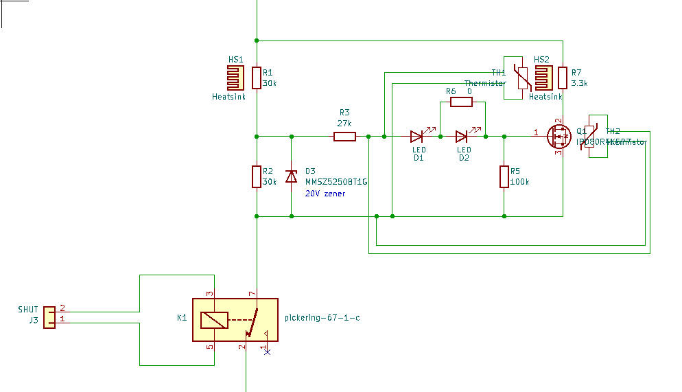 | Formula Student “Discharge Circuit” – Designed to discharge the inverter’s bulk capacitance to a safe voltage quickly. – The rules require the discharge circuit to tolerate the full battery voltage indefinitely, so a single resistor would need to be huge. – I designed a circuit using thermistors and a MOSFET to cut off current flow through the main discharge resistor if it gets above a threshold (but with a larger resistor in parallel as backup) |
